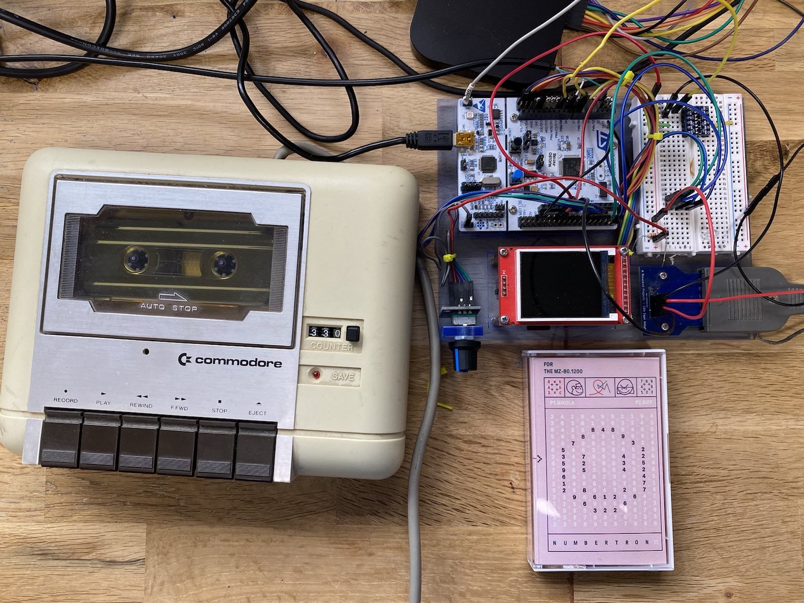
This is an ongoing project for the Sharpe MZ80K computer.
I like Retro and prefer not to use fast loaders/ SD/Compact flash, rather keeping with the original processes.
To that end, I have been coding up a project to decode and encode MZ80K programs to and from tape using a commodore 64 cassette tape deck.
There is an available program to encode the mzf files onto tape using the Commodore 64 tape deck via the PC parallel port.
But…. I wanted the fun of coding this myself, decoding the file structures and building up a device to interface into the tape deck.
Of course, in future, it would be nice to add encoding/deciding for ZXC spectrum, C64 and others, but I though I would start with the MZ80K
Updates:
- 10 April 2024 – Added initial info up to data formats
Im using a NUCLEO-F411RE dev board with STM32 processor and STM32CubeIDE.
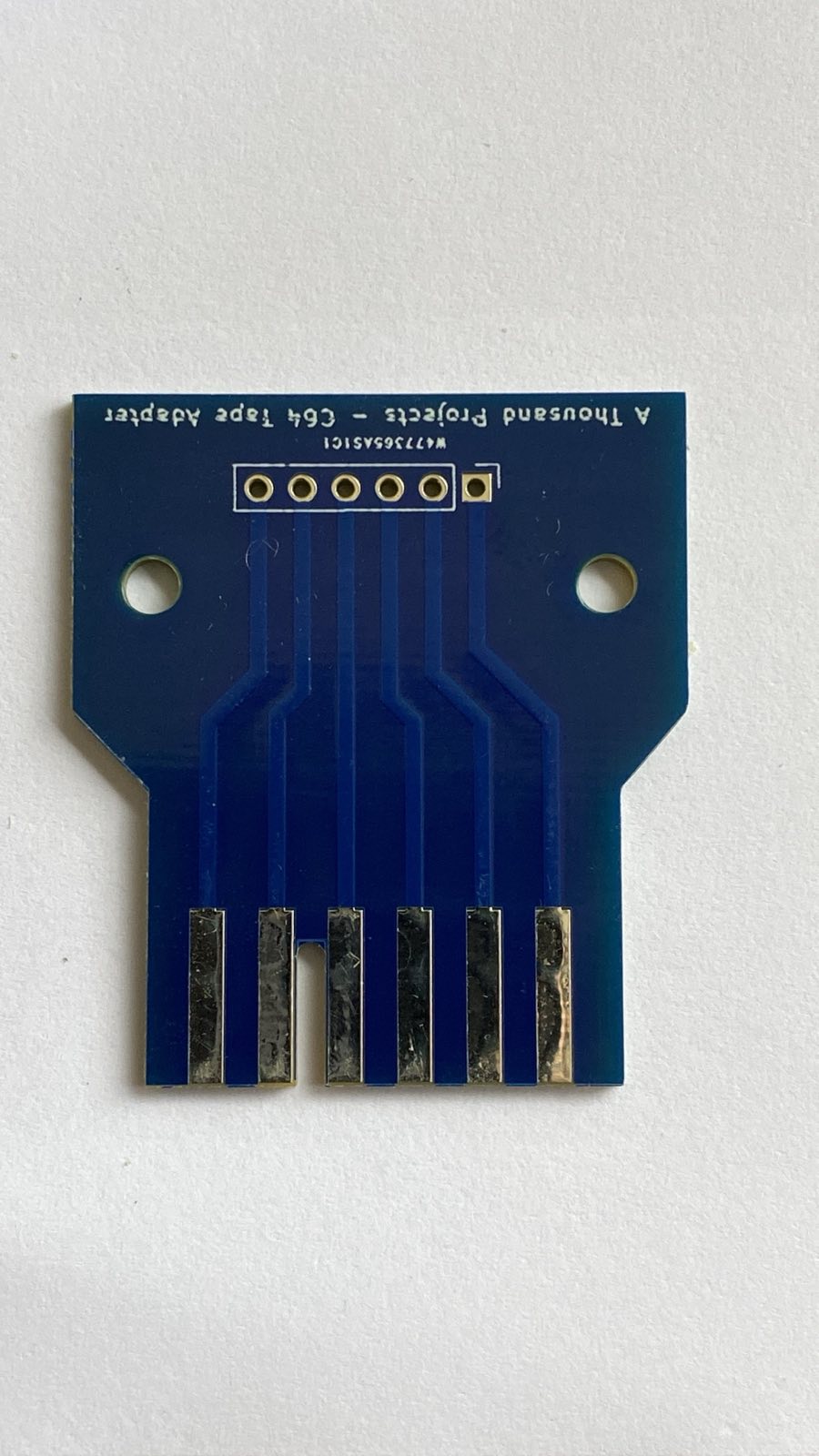
I had some PCB’s made up for the Commodore 64 Tape plug so that it was easy to connect it up. This is single sided, and the plug is double sided, however, its just a mirror so only one side needed.

C64 Pinout
| Pin | Name | Description |
| 1-A | GND | Ground connection |
| 2-B | +5V | 5V dc |
| 3-C | Motor | 6V dc to power the motor. This can be used to enable or disable the motor, otherwise it will run continuously. |
| 4-D | Read | Data Read – 5V digital |
| 5-E | Write | Data Write 5V digital pulse |
| 6-F | Sense | Logical Low to indicate if any of the cassette button have been pressed |

Commodore 64 tape connector
The Cassette port is connected to the NUCLEO-F411 as follows. The selected IO pins are 5V tolerant, though in the final design, I might add a high speed level shifter.
| Nucleo Pin | STM32 Pin | C64 Port Pin | Notes |
| 1-A | |||
| 2-B | |||
| 3-C | Connected to separate 6V Power | ||
| D10 | PB-6 | 4-D | Read input to STM32 |
| CN7 – 21 | PB-7 | 5-E | Write output from STM32 |
| 6-F | Not connected Yet |
Pulse Read Timer Setup
I initially thought I would use the combined PWM input of the timer and use the duty cycle to calculate the pulse width and hence the pule time. However the PWN will wait until the next pulse rise to trigger so that it gets the full pulse length. This does not work for reading just the pulse length. The PWM is really meant for a continuous wave form. I could probably have used timeout more, but in the end I opted for “Input Capture direct mode” using Timer 4.
The system clock is running at 84Mhz so the timer set up is as follow
Prescaler – 84 to bring the timer to 1Mhz
Counter Period 1000 – to allow for timeout detection
Input capture Polarity Selection – Rising Edge
Prescaler division ratio – None
NVIC TIM4 global interrupt – Enabled
Pulse measurement
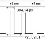
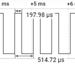
The pulse measurement for the MZ80K is defined by a read time of around 400us after the rising edge of the pulse, the a long pulse being defined at around 380 us and a short pulse being around 200us.
Using my Saleae Logic Ana
 lyzer confirms the pulse lengths which matches much of the documentation I have found online. Of course in the real world, the pulse durations are not perfect and especially with a tape deck. My C64 desk at time of writing this code is old and probably needs to have the belts replaces and a clean up which is on my todo list.
I have set a Long Pulse duration in config for 380us – anything equal or longer is a Long pulse and anything less tahn 380 is decoded as a short pulse. I probably should be a bit more specific about that in the pulse measurement, but it seems to work.
The interrupt is configured to initially trigger on the rising edge and once triggered, reset to trigger on the falling edge. This allows me to measure the pulse length and not worry about the timing on the next incoming pulse.
if (htim->Instance == TIMER_DECODER)
	{

		overflow = 0;

		if (isFirstCaptured == 0)
		{
			ICValueRising = HAL_TIM_ReadCapturedValue(htim, TIMER_DECODER_CHANNEL); // We can discard this as we are resetting the counter
			__HAL_TIM_SET_COUNTER(htim,0);
			__HAL_TIM_SET_CAPTUREPOLARITY(htim,TIM_CHANNEL_1,TIM_INPUTCHANNELPOLARITY_FALLING);
			isFirstCaptured =1;
		}
		else if (isFirstCaptured)
		{
			isFirstCaptured = 0;
			pulseWidth = HAL_TIM_ReadCapturedValue(htim, TIMER_DECODER_CHANNEL);
			__HAL_TIM_SET_CAPTUREPOLARITY(htim,TIMER_DECODER_CHANNEL,TIM_INPUTCHANNELPOLARITY_RISING);


			if (pulseWidth > (PULSE_LONG_TIME * 2 ) && currentExpectation->expectationType != TYPE_EXPECTATION_SYNC)
			{
				return;
			}

			if (pulseWidth > PULSE_LONG_TIME)
			{
				pulseType = PULSE_LONG;
			}
			else
			{
				pulseType = PULSE_SHORT;
			}
Tape Data Format
There is a site that gives the specifications for the format here that has been super useful, but I’ve done my own diagrams for the purpose of documentation.
Both the header and the file are repeated – I guess this is just redundancy which is a good thing. I’m not sure if the system stops after the first file data block if the checksum matches or it it just reads all the data regardless.
Header format

The Header sequence is well defined except for initial Long Gap in the beginning. This is a series of short pulses that is supposed to be 22,000 pulses but when I analysed the raw data off the tape it was anything but that. One of the Tapes (Numbertron) started with a short bust of 6 short pulses, with the 7th staying high for 9ms, then another burst of 198 pulses, then a 17ms low and then a 13202 short pulses. Another tape (AstroDodge) has a clean set of short pulses but only 4432 pulses.
This causes a small issue as I had to handle the initial Long Gap in a different way, allowing for variable blocks and number of pulses. My solution, in the end, was to could a pre-defined number of pulses (I set it to 1000 pulses) and ignore the rest until the Long Tape Mark, which was a definite 40 Long and 40 short pulses.
Data File format

The file format is simpler and the First Gap mark is more accurate, although I treat it in the same way as the header Long Gap.
